# Joystick demo
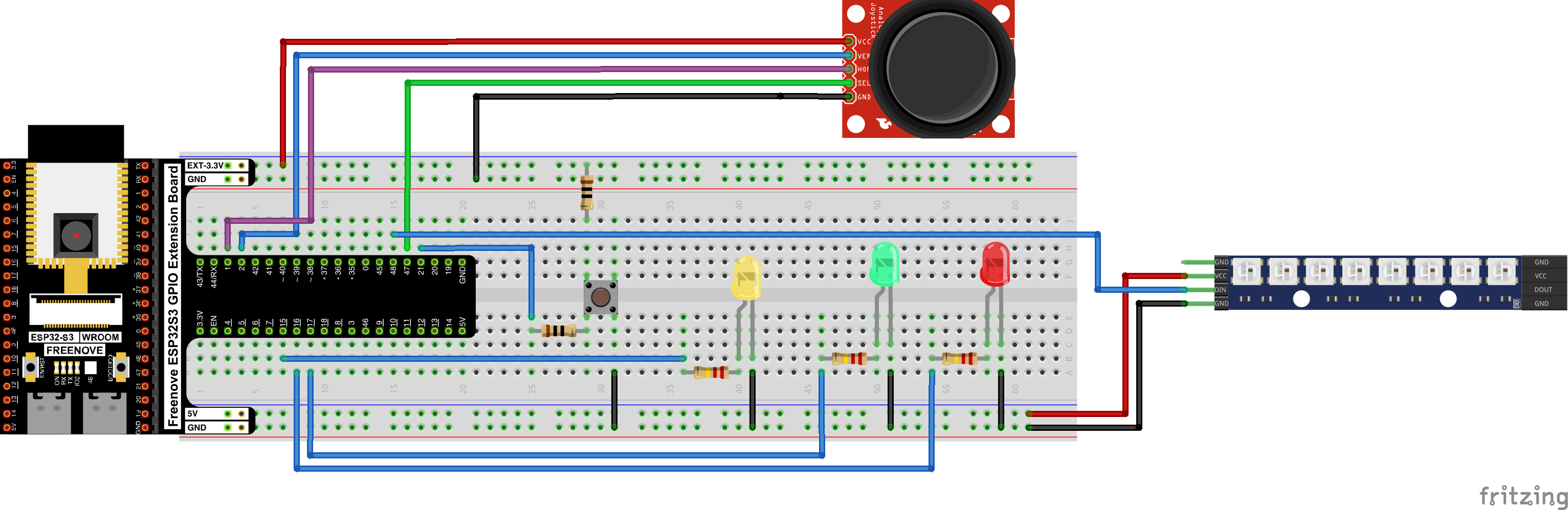
This demo shows using a joystick peripheral to control the position of an LED light on a WS2812 light strip, as well as how to calibrate a joystick, while using PWM driven LEDs to show the relative position of a joystick on its axis and the status of the momentary joystick pushbutton. The breadboard picture above shows a WS2812 horizontal strip, but that's not what I used; mine was a circular LED arrangement, I just couldn't find the right part in Fritzing.
I won't cover the entirety of the code here, but you are welcome to peruse it for yourself: [06-joystick.ino](06-joystick.ino)
[Here is a video of the demonstration running](https://x.com/AKLabsDotNet/status/2063056777768239514)
# Lessons Learned
* Fritzing is time consuming but neat
* I still don't trust C++
* How the RMT peripheral on the ESP32-S3 works and why it is involved when driving WS2812 LED strips
* How to select pin assignments on the ESP32 without relying on the tutorial
* How to calibrate joysticks
## Fritzing
I've been using a breadboard software named [Fritzing](https://fritzing.org/) to do breadboard diagrams for these projects. If the breadboard is unchanged from a tutorial, I'll just copy and paste from the tutorial, but whenever I modify a breadboard, I make up the model in Fritzing. The Freenove folks were cool enough to send the Fritzing components for the devboard I'm using so making the breadboards is relatively easy. Still, translating the breadboard from reality to Fritzing *feels* slow. That's probably just in my head, but I have tended to dread it, kind of like writing documentation. It does have some amount of simulation ability, which I haven't explored yet, but you can apparently do some amount of arduino simulation from within Fritzing, which is neat.
I also haven't gotten the hang of Fritzing's schematic functionality. It can generate schematics from breadboards, which is pretty cool, but I'll be honest the schematics are soup. You have to do a ton of cleanup to make them readable, and I haven't devoted the time yet to figuring out the best way to manage that workflow.
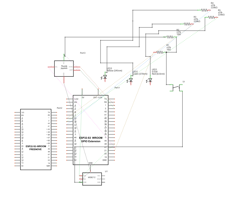
That, uh ... That needs some work.
But if you're getting into this hobby, Fritzing is definitely worth the (small) money.
## I still don't trust C++
To be fair, I give C++ more hate than it deserves. But the way some people write it really does the language no favors.
The WS2812 tutorial(s) use a global variable with an initializer that is called outside of the scope of any function. This is something that you can do in C++ that you really can't do in C, and I tend to think C is right where C++ is wrong.
```arduino
Freenove_ESP32_WS2812 strip = Freenove_ESP32_WS2812(8, PIN_2812, 0, TYPE_GRB);
```
In C the code wouldn't compile, because you can't execute code (beyond setting initializer values with builtin types) outside of a function. In C++, this is valid for constructors. The compiler puts the objects in the data segment, which is nice, as the alternative might be to call `new()` on it and get storage from the heap, which is nasty. But the compiler will generate some magic unspecified initializer function wherein it will call the constructors on the object, before it calls `main()`. And the order of those initializers is not guaranteed, so if A depends on B, you may be shit out of luck. And I especially don't trust global initializers that seem to be touching hardware. The whole thing just feels *wrong*.
 I chose instead to force the initializer for the global variable to happen during the `init2812` routine, which is called during `setup`.
```arduino
alignas(Freenove_ESP32_WS2812) uint8_t strip_storage[sizeof(Freenove_ESP32_WS2812)];
Freenove_ESP32_WS2812 *strip;
int init2812(Freenove_ESP32_WS2812 **strip)
{
Freenove_ESP32_WS2812 *obj = new(strip_storage) Freenove_ESP32_WS2812(8, PIN_2812, 0, TYPE_GRB);
if ( obj == NULL ) {
ERROR(ERRNO_NULLPOINTER);
}
obj->setBrightness(10);
obj->begin();
*strip = obj;
return ERRNO_SUCCESS;
}
```
With this pattern, I get the global variable, that lives in the data segment, that is initialized exactly when I want it to be initialized. The downside (some might say) is that I'm stuck with using a pointer to reference the object in memory. Someone who fears pointers could use `std::optional` and `emplace()` to do the same thing, assuming that their toolchain supports it. But I feel like that's adding complexity in layers of abstraction. It doesn't get much simpler than saying "This object lives in memory *right over there* and here is a pointer to it".
## Selecting pin assignments: read the datasheets
Up until now I've been using whatever pins the tutorial chose because, well, I had enough to figure out while getting my fundamental electronics lessons. But ...
I chose instead to force the initializer for the global variable to happen during the `init2812` routine, which is called during `setup`.
```arduino
alignas(Freenove_ESP32_WS2812) uint8_t strip_storage[sizeof(Freenove_ESP32_WS2812)];
Freenove_ESP32_WS2812 *strip;
int init2812(Freenove_ESP32_WS2812 **strip)
{
Freenove_ESP32_WS2812 *obj = new(strip_storage) Freenove_ESP32_WS2812(8, PIN_2812, 0, TYPE_GRB);
if ( obj == NULL ) {
ERROR(ERRNO_NULLPOINTER);
}
obj->setBrightness(10);
obj->begin();
*strip = obj;
return ERRNO_SUCCESS;
}
```
With this pattern, I get the global variable, that lives in the data segment, that is initialized exactly when I want it to be initialized. The downside (some might say) is that I'm stuck with using a pointer to reference the object in memory. Someone who fears pointers could use `std::optional` and `emplace()` to do the same thing, assuming that their toolchain supports it. But I feel like that's adding complexity in layers of abstraction. It doesn't get much simpler than saying "This object lives in memory *right over there* and here is a pointer to it".
## Selecting pin assignments: read the datasheets
Up until now I've been using whatever pins the tutorial chose because, well, I had enough to figure out while getting my fundamental electronics lessons. But ...
 When you're following tutorials it's easy to assume "Pin X does Y thing because that's what the tutorial connected me to", and it's especially easy to think "Pin X **only** does Y thing", or "You **always** do Y thing with Pin X". This is almost never true. Each microcontroller has a datasheet from the manufacturer that tells you what all the different pins on the MCU do. The particular dev board you're using should also have a datasheet (or at least a pinout) that shows how the dev board maps all of the microcontroller pins to the devboard pins. Using these references will show you that, in fact, you can just lots of pins for lots of different functions, and that depending on how the chip is set up, a given pin may be overloaded with several different features - and that these usually can't be used together at the same time.
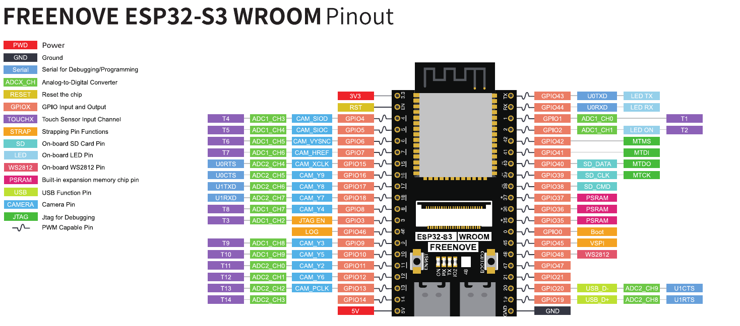
For example, here is the Freenove ESP32-S3 WROOM pinout from Freenove, the manufacturer of the dev board I'm using
When you're following tutorials it's easy to assume "Pin X does Y thing because that's what the tutorial connected me to", and it's especially easy to think "Pin X **only** does Y thing", or "You **always** do Y thing with Pin X". This is almost never true. Each microcontroller has a datasheet from the manufacturer that tells you what all the different pins on the MCU do. The particular dev board you're using should also have a datasheet (or at least a pinout) that shows how the dev board maps all of the microcontroller pins to the devboard pins. Using these references will show you that, in fact, you can just lots of pins for lots of different functions, and that depending on how the chip is set up, a given pin may be overloaded with several different features - and that these usually can't be used together at the same time.
For example, here is the Freenove ESP32-S3 WROOM pinout from Freenove, the manufacturer of the dev board I'm using
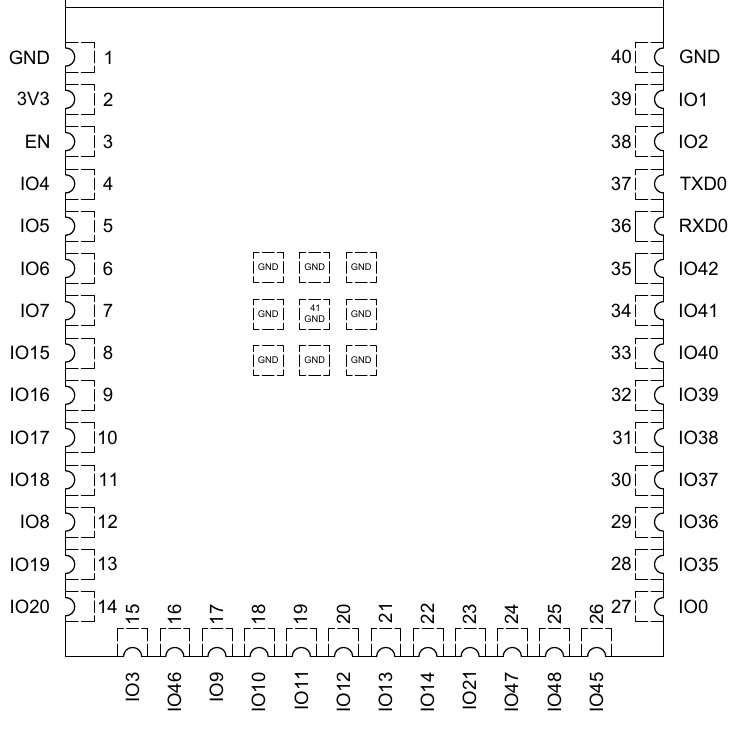
 And here is some of the pin reference documentation from Espressif on the ESP32-S3 chip itself that lives on the devboard (click each image for higher resolution - this can alos be found in chapter 2 of the datasheet from Espressif). This should tell us that the pins on our devboard aren't on the same place as the ones on the ESP32-S3 itself, they may not even be numbered the same, and the board vendor may not actually choose to expose the entire package. At least the vendor and the chip manufacturer should be using the same *names* for the pins (`GPIOxx` for example) so we can cross reference them.
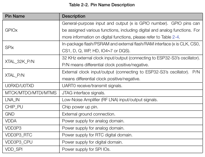
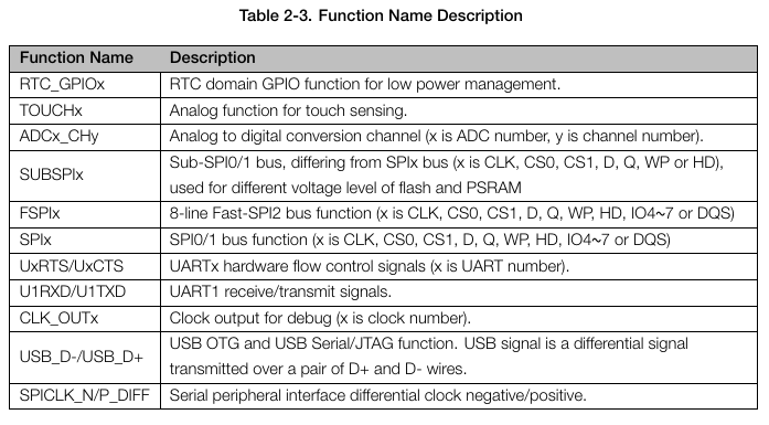
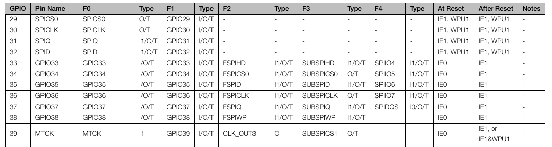 ... The datasheet goes on to explain that not only might these pins have multiple different functions, but that those functions:
* Might be input only, output only, or both
* May or may not be high impedance
* What the input signal of unused functions on a given pin will read when checkeed
* What is the default state of the pin after reset
* What is the drive strength of the signal on the pin (how many milliamps)
* What glitches occur on which pins at powerup (high level, low level, pull up, pull down) and how long does that glitch last
* Which pins have mappings to which in-package Flash/SRAM pins, which makes these pins unsuitable for other usage
It's also worth pointing out that, in order to get the most complete picture of the pin configuration, I actually had to consult THREE different datasheets:
* The Espressif ESP32-S3 datasheet
* The Espressif ESP32-S3 WROOM datasheet (the specific ESP32-S3 package my dev board is using, which has some differences vs a regular ESP32-S3)
* The Freenove devboard documentation (such as it is)
Using this information, I was able to make pin selections for my code, while noting some incompatibilities if we were to turn on other functions. I knew I was going to need:
* 2 input pins on an ADC controller for the joystick axes
* 2 output pins on a PWM controller for the joystick axes LED lights
* Something for the WS2812 signal
* 2 GPIOs, one for the calibration button, one for the joystick button
```
// Pin 21 is GPIO only
#define PIN_BUTTON 21 // Calibration button
// Apparently there is a dedicated 2812 controller in the ESP32-S3 that lives on this pin
// and this pin only.
#define PIN_2812 48 // Data bus for the 2812 LED
// These pins are shared with the second ADC unit. We're not using that unit in this project
// but for future projects as my boards become more dense I need to remember that each pin
// choice is a tradeoff. At a certain point we run out of available pins for adding stuff on,
// and have to start getting creative about how we use the pins we have left.
#define PIN_LED_X 16 // Red X axis LED
#define PIN_LED_Y 18 // Green Y axis LED
#define PIN_LED_Z 15 // Yellow Z axis LED (button)
// Pins 1 and 2 are on ADC channel 0 and 1.
#define PIN_JOY_X 1
#define PIN_JOY_Y 2
// Pin 47 is GPIO only
#define PIN_JOY_Z 47
```
Interstingly enough, the Freenove documentation labels pin 48 on their dev board as featuring some kind of dedicated WS2812 controller. However the text of their C tutorial says that the WS2812 is driven through the RMT controller (more on that in a minute). The ESP32-S3 WROOM MCU on this devboard doesn't even list 48 pins on the datasheet (though the parent ESP32-S3 datasheet does, so I guess the parent datasheet is authoritative? Maybe the missing pins are in the WROOM's "keep out zone"). When you're designing a board, you may need to ask questions like, "how will this dev board map to the real world when my code is driving the MCU on a different PCB? Will my assumptions about pins be correct? Will the peripherals be in the same place and work the same way? *Will this peripheral I'm using on the dev board even be there*?"
Hopefully the documentation makes all of that clear. Sometimes it does not, and you have to go spelunking, or ask the vendor questions directly. In the case of the WS2812 mystery pin 48, we can see in the ESP32-S3 datasheet chapter 3 (peripheral pin configurations) that the remote control peripheral (RMT) can be assigned to "any GPIO pin", depending on how it is initialized. So it looks like the Freenove WS2812 driver library is simply forcing the assignment of one of the RMT channels to pin 48, and that's why the tutorials and datasheets list pin 48 as the home for WS2812.
## WS2812s and the RMT
The WS2812 is a series of LEDs on a strip, which can be controlled by sending a compact stream of data to the strip, and each LED takes its own data before forwarding on the rest. This allows you to control each LED individually in a theoretically endless string of LEDs with very little hardware overhead. In the particular example here, the WS2812 strip is arranged as an octagon of LEDs on a square PCB package with one `V+` line, one `GND` line, and one `S`(ignal) line.
Oh, and you control it using the **infrared remote control module** on the ESP32.
... The datasheet goes on to explain that not only might these pins have multiple different functions, but that those functions:
* Might be input only, output only, or both
* May or may not be high impedance
* What the input signal of unused functions on a given pin will read when checkeed
* What is the default state of the pin after reset
* What is the drive strength of the signal on the pin (how many milliamps)
* What glitches occur on which pins at powerup (high level, low level, pull up, pull down) and how long does that glitch last
* Which pins have mappings to which in-package Flash/SRAM pins, which makes these pins unsuitable for other usage
It's also worth pointing out that, in order to get the most complete picture of the pin configuration, I actually had to consult THREE different datasheets:
* The Espressif ESP32-S3 datasheet
* The Espressif ESP32-S3 WROOM datasheet (the specific ESP32-S3 package my dev board is using, which has some differences vs a regular ESP32-S3)
* The Freenove devboard documentation (such as it is)
Using this information, I was able to make pin selections for my code, while noting some incompatibilities if we were to turn on other functions. I knew I was going to need:
* 2 input pins on an ADC controller for the joystick axes
* 2 output pins on a PWM controller for the joystick axes LED lights
* Something for the WS2812 signal
* 2 GPIOs, one for the calibration button, one for the joystick button
```
// Pin 21 is GPIO only
#define PIN_BUTTON 21 // Calibration button
// Apparently there is a dedicated 2812 controller in the ESP32-S3 that lives on this pin
// and this pin only.
#define PIN_2812 48 // Data bus for the 2812 LED
// These pins are shared with the second ADC unit. We're not using that unit in this project
// but for future projects as my boards become more dense I need to remember that each pin
// choice is a tradeoff. At a certain point we run out of available pins for adding stuff on,
// and have to start getting creative about how we use the pins we have left.
#define PIN_LED_X 16 // Red X axis LED
#define PIN_LED_Y 18 // Green Y axis LED
#define PIN_LED_Z 15 // Yellow Z axis LED (button)
// Pins 1 and 2 are on ADC channel 0 and 1.
#define PIN_JOY_X 1
#define PIN_JOY_Y 2
// Pin 47 is GPIO only
#define PIN_JOY_Z 47
```
Interstingly enough, the Freenove documentation labels pin 48 on their dev board as featuring some kind of dedicated WS2812 controller. However the text of their C tutorial says that the WS2812 is driven through the RMT controller (more on that in a minute). The ESP32-S3 WROOM MCU on this devboard doesn't even list 48 pins on the datasheet (though the parent ESP32-S3 datasheet does, so I guess the parent datasheet is authoritative? Maybe the missing pins are in the WROOM's "keep out zone"). When you're designing a board, you may need to ask questions like, "how will this dev board map to the real world when my code is driving the MCU on a different PCB? Will my assumptions about pins be correct? Will the peripherals be in the same place and work the same way? *Will this peripheral I'm using on the dev board even be there*?"
Hopefully the documentation makes all of that clear. Sometimes it does not, and you have to go spelunking, or ask the vendor questions directly. In the case of the WS2812 mystery pin 48, we can see in the ESP32-S3 datasheet chapter 3 (peripheral pin configurations) that the remote control peripheral (RMT) can be assigned to "any GPIO pin", depending on how it is initialized. So it looks like the Freenove WS2812 driver library is simply forcing the assignment of one of the RMT channels to pin 48, and that's why the tutorials and datasheets list pin 48 as the home for WS2812.
## WS2812s and the RMT
The WS2812 is a series of LEDs on a strip, which can be controlled by sending a compact stream of data to the strip, and each LED takes its own data before forwarding on the rest. This allows you to control each LED individually in a theoretically endless string of LEDs with very little hardware overhead. In the particular example here, the WS2812 strip is arranged as an octagon of LEDs on a square PCB package with one `V+` line, one `GND` line, and one `S`(ignal) line.
Oh, and you control it using the **infrared remote control module** on the ESP32.
 The WS2812 is controlled with [a wierd single line protocol](https://cdn-shop.adafruit.com/datasheets/WS2812B.pdf) that's really efficient but very sensitive to timing. The whole thing works off of PWM signals on the signal wire, and there is no clock synchronization. Basically every LED receives a 24 bit color value (in RGB or GRB or whatever format is appropriate), then there's a pause, then the next value is sent for the next LED. If you've got 8 LEDs in series, you get 8 24 bit values, in order.
```
LED8val LED7val LED6val LED5val LED4val LED3val LED2val LED1val
```
The 24 bits for each LED RGB/GBR value are sent in reverse order (bit 23 is sent first, down to bit 0). What's really wierd is that the bits in the value are sent using pulse width modulation. Each bit in a value consists of some portion of a full duty cycle being high, and some other portion being low. If the duty cycle is empty, then there is no bit on the wire during that time.
```
0 bit:
┌─┐
│ │
│ └─────────
└───────────
0.4µs 0.85µs
1 bit:
┌──────┐
│ │
│ └────
└───────────
0.8µs 0.45µs
```
Apparently this kind of task is what the remote control peripheral was made for. It's a pulse encoder, and what you do is you fill a buffer in RAM with the values you want sent, tell it to go, and it will take care of performing all the pulse width encoding of those values for you. (Or, in the reverse: it receives and decodes pulses, and puts them in memory for you.) You could do it yourself on a GPIO pin manually sending the PWM signals but it is very easy to get wrong, as you can see with the timing data; and even if your code was perfect, if you're running on a multitasking environment on the ESP32, you're basically screwed. Instead we can just send the data to the independent hardware peripheral, and the CPU goes along its merry way doing other things.
Unlike something like I2C or SPI where every LED would need its own address on the bus, and a lot more data lines, this protocol allows us to simply shove the data down the pipe and allow each LED to act as a filter for the one after it. FOr example, LED1 consumes the first 24 bits of information in the signal, and then passes everything else. LED2 consumes the next 24 and passes everything else, and so on, and so on. It's kind of odd but very efficient.
Anyway, with our circular array of 8 LEDs on the WS2812 strip, and with our ability to control every LED individually, we can light up a single LED on the array according to the X/Y values of the joystick, allowing us to move the light around the circle with the joystick.
All this happens inside the `display2812` function. First we turn off all the LEDs on the strip
```arduino
strip->setLedColorData(LED_2812_LEFT, 0, 0, 0);
strip->setLedColorData(LED_2812_TOPLEFT, 0, 0, 0);
strip->setLedColorData(LED_2812_TOP, 0, 0, 0);
strip->setLedColorData(LED_2812_TOPRIGHT, 0, 0, 0);
strip->setLedColorData(LED_2812_RIGHT, 0, 0, 0);
strip->setLedColorData(LED_2812_BOTTOMRIGHT, 0, 0, 0);
strip->setLedColorData(LED_2812_BOTTOM, 0, 0, 0);
strip->setLedColorData(LED_2812_BOTTOMLEFT, 0, 0, 0);
```
... then we turn on just the one we want according to the joystick position
```arduino
if ( ( js->state & JOYSTICK_STATE_READY ) == JOYSTICK_STATE_READY ) {
// Light up the correct LED_2812_* depending on the value of the X/Y axes on the joystick
if ( js->x.position < 1024 && (js->y.position < 3072 && js->y.position > 1024) ) {
strip->setLedColorData(LED_2812_LEFT, 128, 128, 128);
} else if ( js->x.position < 1024 && js->y.position < 1024 ) {
strip->setLedColorData(LED_2812_TOPLEFT, 128, 128, 128);
} else if ( ( js->x.position > 1024 && js->x.position < 3072 ) && js->y.position < 1024 ) {
strip->setLedColorData(LED_2812_TOP, 128, 128, 128);
} else if ( js->x.position > 3072 && js->y.position < 1024 ) {
strip->setLedColorData(LED_2812_TOPRIGHT, 128, 128, 128);
} else if ( js->x.position > 3072 && ( js->y.position < 3072 && js->y.position > 1024) ) {
strip->setLedColorData(LED_2812_RIGHT, 128, 128, 128);
} else if ( js->x.position > 3072 && js->y.position > 3072 ) {
strip->setLedColorData(LED_2812_BOTTOMRIGHT, 128, 128, 128);
} else if ( ( js->x.position > 1024 && js->x.position < 3072 ) && js->y.position > 3072 ) {
strip->setLedColorData(LED_2812_BOTTOM, 128, 128, 128);
} else if ( js->x.position < 1024 && js->y.position > 3072 ) {
strip->setLedColorData(LED_2812_BOTTOMLEFT, 128, 128, 128);
}
}
strip->show();
```
The code complexity is about the same as if we were using individual LEDs on the board, because I can still (effectively) control each one in the strip individually, thanks to the WS2812 driver code from Freenove that I'm using here. But the ability to do it all with one `+5v`, one `GND` and one `Data` wire on the board is really cool.
## Calibrating joysticks
I implemented calibration logic in my code, but it was a bit lazy, and to be honest, it doesn't do what real calibration typically does. But by the time I got here, I was just ready to move on to the next project. When you press the calibration button, the calibration routine starts which continually samples over a period of time. It creates a deadzone according to the lowest and highest values seen on each axes during this time. When future joystick reads occur, anything within this deadzone are counted as being at the center of the axis. Really I did this to account for potential wobble in the joystick I hooked to the arduino, but that was unnecessary, it was remarkably stable in the center.
The calibration data lives on the JoystickAxis datastructure
```arduino
typedef struct Calibration {
// When did calibration start
uint32_t start_time;
// Low calibration range
uint32_t low;
// High calibration range
uint32_t high;
// How long we should sample values on this joystick
uint32_t stable_time;
} Calibration;
typedef struct JoystickAxis {
// What ADC pin is this joystick axis connected to
uint8_t pin;
// Calibration data
Calibration calibration;
// Position as of the last read time.
uint32_t position;
} JoystickAxis;
```
A Joystick itself is represented as a collection of axis measurements and a button
```arduino
typedef struct Joystick {
// X axis data
JoystickAxis x;
// Y axis data
JoystickAxis y;
// This is the Z axis switch on the joystick control
Button button;
// What is the state of this joystick (bitmask of JOYSTICK_STATE_*)
uint8_t state;
} Joystick;
```
The calibration method manages the state of the joystick in question, performing calibration over a given period of time
```arduino
// Calibrate a given joystick
int calibrateJoystick(Joystick *js)
{
uint32_t x = 0;
uint32_t y = 0;
uint32_t curmillis = 0;
if ( js == NULL ) {
ERROR(ERRNO_NULLPOINTER);
}
curmillis = millis();
if ( js->x.calibration.start_time == 0 || js->y.calibration.start_time == 0 ) {
// Starting a new calibration cycle
Serial.printf("Starting a new calibration cycle\n");
js->x.calibration.low = 65535;
js->x.calibration.high = 0;
js->y.calibration.low = 65535;
js->y.calibration.high = 0;
js->x.calibration.start_time = curmillis;
js->y.calibration.start_time = curmillis;
return ERRNO_SUCCESS;
}
if ( (curmillis - js->x.calibration.start_time) >= js->x.calibration.stable_time ) {
js->state = JOYSTICK_STATE_CALIBRATED;
js->x.calibration.start_time = 0;
js->y.calibration.start_time = 0;
Serial.printf("Calibrated joystick to x: <%d, %d> y <%d, %d>\n",
js->x.calibration.low,
js->x.calibration.high,
js->y.calibration.low,
js->y.calibration.high);
return ERRNO_SUCCESS;
}
x = analogRead(js->x.pin);
if ( x < js->x.calibration.low ) {
js->x.calibration.low = x;
} else if ( x > js->x.calibration.high ) {
js->x.calibration.high = x;
}
y = analogRead(js->y.pin);
if ( y < js->y.calibration.low ) {
js->y.calibration.low = y;
} else if ( y > js->y.calibration.high ) {
js->y.calibration.high = y;
}
return ERRNO_SUCCESS;
}
```
The method for reading joystick axes and buttons is only called when the joystick has a `CALIBRATED` status
```arduino
if ( ( js.state & JOYSTICK_STATE_CALIBRATED) == JOYSTICK_STATE_CALIBRATED ) {
if ( readJoystick(&js) != ERRNO_SUCCESS ) {
Serial.printf("Failed to read joystick state : %d\n", errno);
}
}
```
... and the joystick read function performs the primitive snap-to-center lazy calibration:
```arduino
int readJoystick(Joystick *js)
{
uint32_t adcvalue = 0;
if ( js == NULL ) {
ERROR(ERRNO_NULLPOINTER);
}
js->state = js->state | JOYSTICK_STATE_READING;
adcvalue = analogRead(js->x.pin);
if ( adcvalue < js->x.calibration.low || adcvalue > js->x.calibration.high ) {
js->x.position = adcvalue;
} else {
// Snap to center
js->x.position = 2048;
}
adcvalue = analogRead(js->y.pin);
if ( adcvalue < js->y.calibration.low || adcvalue > js->y.calibration.high ) {
js->y.position = adcvalue;
} else {
// Snap to center
js->y.position = 2048;
}
//Serial.printf("Joystick x %d y %d\n", js->x.position, js->y.position);
readButton(&js->button);
js->state = js->state ^ JOYSTICK_STATE_READING;
if ( errno != ERRNO_SUCCESS ) {
Serial.printf("Failed to read joystick button : %d\n", errno);
return errno;
}
js->state = js->state | JOYSTICK_STATE_READY;
return ERRNO_SUCCESS;
}
```
A real calibration routine is more advanced and allows the center to actually move. As it samples, it figures out where the center of the sample average range is, and future joystick reads return the axis movement relative to that center location. My calibration routine here can't do that. I considered changing this, but again, that was outside of the original design goal for the calibration routine.
## Closing Thoughts
This project was fun. It was the first one I designed fully independently of tutorials (except for the PIN 48 assignment and library syntax for the WS2812), and I got a lot of reusable code out of the deal. The entire joystick and button subsystem can be reused in future projects. And I think one of my next projects is going to be connecting the joystick to a Linux PC as a human interface device, and seeing if I can control some [`libakgl`](https://source.starfort.tech/andrew/libakgl) demos with it.
The WS2812 is controlled with [a wierd single line protocol](https://cdn-shop.adafruit.com/datasheets/WS2812B.pdf) that's really efficient but very sensitive to timing. The whole thing works off of PWM signals on the signal wire, and there is no clock synchronization. Basically every LED receives a 24 bit color value (in RGB or GRB or whatever format is appropriate), then there's a pause, then the next value is sent for the next LED. If you've got 8 LEDs in series, you get 8 24 bit values, in order.
```
LED8val LED7val LED6val LED5val LED4val LED3val LED2val LED1val
```
The 24 bits for each LED RGB/GBR value are sent in reverse order (bit 23 is sent first, down to bit 0). What's really wierd is that the bits in the value are sent using pulse width modulation. Each bit in a value consists of some portion of a full duty cycle being high, and some other portion being low. If the duty cycle is empty, then there is no bit on the wire during that time.
```
0 bit:
┌─┐
│ │
│ └─────────
└───────────
0.4µs 0.85µs
1 bit:
┌──────┐
│ │
│ └────
└───────────
0.8µs 0.45µs
```
Apparently this kind of task is what the remote control peripheral was made for. It's a pulse encoder, and what you do is you fill a buffer in RAM with the values you want sent, tell it to go, and it will take care of performing all the pulse width encoding of those values for you. (Or, in the reverse: it receives and decodes pulses, and puts them in memory for you.) You could do it yourself on a GPIO pin manually sending the PWM signals but it is very easy to get wrong, as you can see with the timing data; and even if your code was perfect, if you're running on a multitasking environment on the ESP32, you're basically screwed. Instead we can just send the data to the independent hardware peripheral, and the CPU goes along its merry way doing other things.
Unlike something like I2C or SPI where every LED would need its own address on the bus, and a lot more data lines, this protocol allows us to simply shove the data down the pipe and allow each LED to act as a filter for the one after it. FOr example, LED1 consumes the first 24 bits of information in the signal, and then passes everything else. LED2 consumes the next 24 and passes everything else, and so on, and so on. It's kind of odd but very efficient.
Anyway, with our circular array of 8 LEDs on the WS2812 strip, and with our ability to control every LED individually, we can light up a single LED on the array according to the X/Y values of the joystick, allowing us to move the light around the circle with the joystick.
All this happens inside the `display2812` function. First we turn off all the LEDs on the strip
```arduino
strip->setLedColorData(LED_2812_LEFT, 0, 0, 0);
strip->setLedColorData(LED_2812_TOPLEFT, 0, 0, 0);
strip->setLedColorData(LED_2812_TOP, 0, 0, 0);
strip->setLedColorData(LED_2812_TOPRIGHT, 0, 0, 0);
strip->setLedColorData(LED_2812_RIGHT, 0, 0, 0);
strip->setLedColorData(LED_2812_BOTTOMRIGHT, 0, 0, 0);
strip->setLedColorData(LED_2812_BOTTOM, 0, 0, 0);
strip->setLedColorData(LED_2812_BOTTOMLEFT, 0, 0, 0);
```
... then we turn on just the one we want according to the joystick position
```arduino
if ( ( js->state & JOYSTICK_STATE_READY ) == JOYSTICK_STATE_READY ) {
// Light up the correct LED_2812_* depending on the value of the X/Y axes on the joystick
if ( js->x.position < 1024 && (js->y.position < 3072 && js->y.position > 1024) ) {
strip->setLedColorData(LED_2812_LEFT, 128, 128, 128);
} else if ( js->x.position < 1024 && js->y.position < 1024 ) {
strip->setLedColorData(LED_2812_TOPLEFT, 128, 128, 128);
} else if ( ( js->x.position > 1024 && js->x.position < 3072 ) && js->y.position < 1024 ) {
strip->setLedColorData(LED_2812_TOP, 128, 128, 128);
} else if ( js->x.position > 3072 && js->y.position < 1024 ) {
strip->setLedColorData(LED_2812_TOPRIGHT, 128, 128, 128);
} else if ( js->x.position > 3072 && ( js->y.position < 3072 && js->y.position > 1024) ) {
strip->setLedColorData(LED_2812_RIGHT, 128, 128, 128);
} else if ( js->x.position > 3072 && js->y.position > 3072 ) {
strip->setLedColorData(LED_2812_BOTTOMRIGHT, 128, 128, 128);
} else if ( ( js->x.position > 1024 && js->x.position < 3072 ) && js->y.position > 3072 ) {
strip->setLedColorData(LED_2812_BOTTOM, 128, 128, 128);
} else if ( js->x.position < 1024 && js->y.position > 3072 ) {
strip->setLedColorData(LED_2812_BOTTOMLEFT, 128, 128, 128);
}
}
strip->show();
```
The code complexity is about the same as if we were using individual LEDs on the board, because I can still (effectively) control each one in the strip individually, thanks to the WS2812 driver code from Freenove that I'm using here. But the ability to do it all with one `+5v`, one `GND` and one `Data` wire on the board is really cool.
## Calibrating joysticks
I implemented calibration logic in my code, but it was a bit lazy, and to be honest, it doesn't do what real calibration typically does. But by the time I got here, I was just ready to move on to the next project. When you press the calibration button, the calibration routine starts which continually samples over a period of time. It creates a deadzone according to the lowest and highest values seen on each axes during this time. When future joystick reads occur, anything within this deadzone are counted as being at the center of the axis. Really I did this to account for potential wobble in the joystick I hooked to the arduino, but that was unnecessary, it was remarkably stable in the center.
The calibration data lives on the JoystickAxis datastructure
```arduino
typedef struct Calibration {
// When did calibration start
uint32_t start_time;
// Low calibration range
uint32_t low;
// High calibration range
uint32_t high;
// How long we should sample values on this joystick
uint32_t stable_time;
} Calibration;
typedef struct JoystickAxis {
// What ADC pin is this joystick axis connected to
uint8_t pin;
// Calibration data
Calibration calibration;
// Position as of the last read time.
uint32_t position;
} JoystickAxis;
```
A Joystick itself is represented as a collection of axis measurements and a button
```arduino
typedef struct Joystick {
// X axis data
JoystickAxis x;
// Y axis data
JoystickAxis y;
// This is the Z axis switch on the joystick control
Button button;
// What is the state of this joystick (bitmask of JOYSTICK_STATE_*)
uint8_t state;
} Joystick;
```
The calibration method manages the state of the joystick in question, performing calibration over a given period of time
```arduino
// Calibrate a given joystick
int calibrateJoystick(Joystick *js)
{
uint32_t x = 0;
uint32_t y = 0;
uint32_t curmillis = 0;
if ( js == NULL ) {
ERROR(ERRNO_NULLPOINTER);
}
curmillis = millis();
if ( js->x.calibration.start_time == 0 || js->y.calibration.start_time == 0 ) {
// Starting a new calibration cycle
Serial.printf("Starting a new calibration cycle\n");
js->x.calibration.low = 65535;
js->x.calibration.high = 0;
js->y.calibration.low = 65535;
js->y.calibration.high = 0;
js->x.calibration.start_time = curmillis;
js->y.calibration.start_time = curmillis;
return ERRNO_SUCCESS;
}
if ( (curmillis - js->x.calibration.start_time) >= js->x.calibration.stable_time ) {
js->state = JOYSTICK_STATE_CALIBRATED;
js->x.calibration.start_time = 0;
js->y.calibration.start_time = 0;
Serial.printf("Calibrated joystick to x: <%d, %d> y <%d, %d>\n",
js->x.calibration.low,
js->x.calibration.high,
js->y.calibration.low,
js->y.calibration.high);
return ERRNO_SUCCESS;
}
x = analogRead(js->x.pin);
if ( x < js->x.calibration.low ) {
js->x.calibration.low = x;
} else if ( x > js->x.calibration.high ) {
js->x.calibration.high = x;
}
y = analogRead(js->y.pin);
if ( y < js->y.calibration.low ) {
js->y.calibration.low = y;
} else if ( y > js->y.calibration.high ) {
js->y.calibration.high = y;
}
return ERRNO_SUCCESS;
}
```
The method for reading joystick axes and buttons is only called when the joystick has a `CALIBRATED` status
```arduino
if ( ( js.state & JOYSTICK_STATE_CALIBRATED) == JOYSTICK_STATE_CALIBRATED ) {
if ( readJoystick(&js) != ERRNO_SUCCESS ) {
Serial.printf("Failed to read joystick state : %d\n", errno);
}
}
```
... and the joystick read function performs the primitive snap-to-center lazy calibration:
```arduino
int readJoystick(Joystick *js)
{
uint32_t adcvalue = 0;
if ( js == NULL ) {
ERROR(ERRNO_NULLPOINTER);
}
js->state = js->state | JOYSTICK_STATE_READING;
adcvalue = analogRead(js->x.pin);
if ( adcvalue < js->x.calibration.low || adcvalue > js->x.calibration.high ) {
js->x.position = adcvalue;
} else {
// Snap to center
js->x.position = 2048;
}
adcvalue = analogRead(js->y.pin);
if ( adcvalue < js->y.calibration.low || adcvalue > js->y.calibration.high ) {
js->y.position = adcvalue;
} else {
// Snap to center
js->y.position = 2048;
}
//Serial.printf("Joystick x %d y %d\n", js->x.position, js->y.position);
readButton(&js->button);
js->state = js->state ^ JOYSTICK_STATE_READING;
if ( errno != ERRNO_SUCCESS ) {
Serial.printf("Failed to read joystick button : %d\n", errno);
return errno;
}
js->state = js->state | JOYSTICK_STATE_READY;
return ERRNO_SUCCESS;
}
```
A real calibration routine is more advanced and allows the center to actually move. As it samples, it figures out where the center of the sample average range is, and future joystick reads return the axis movement relative to that center location. My calibration routine here can't do that. I considered changing this, but again, that was outside of the original design goal for the calibration routine.
## Closing Thoughts
This project was fun. It was the first one I designed fully independently of tutorials (except for the PIN 48 assignment and library syntax for the WS2812), and I got a lot of reusable code out of the deal. The entire joystick and button subsystem can be reused in future projects. And I think one of my next projects is going to be connecting the joystick to a Linux PC as a human interface device, and seeing if I can control some [`libakgl`](https://source.starfort.tech/andrew/libakgl) demos with it.